SUN Monitore Modifikation
Last update: 30-Nov-1998
The following SUN monitors are able to use separate sync (PC-style) as shipped,
no modification necessary.
- 365-1335 New Multisync 20" Premium monitor (Sony Model GDM 20E20)
- 365-1338 New Multisync 17" Premium monitor (Sony Model GDM 17E20)
- 365-1343 New Multisync 17" Entry level monitor
And the good news is
that these monitor use the same pinout as the modified 17" below, so you can
keep your cable that took so long to make.
And even more good news, SUN
now have an adapter cable to use the above monitors with a PC and it is suitable
for the modified 17" below.
The SUN-Express part# of this adapter cable is:
530-2357.
An adapter cable of the reverse kind (PC monitor to a SUN) is also
available, SUN Express # 130-3034.
Converting 17" Sony GDM 17E10 Color Monitor to PC And SUN use

The 17" is a multisync monitor capable of syncing to horizontal
frequencies from 30 kHz to 82 kHz, and vertical 50-150 Hz.

The Sun model uses combined sync on pin 5 of the 13W3 connector. Most
PC graphics boards generate separate hsync and vsync so the monitor
must be modified to use separate sync.

After modification, the monitor will be able to sync either on
composite sync or separate sync, so there will be no problem using it
with a Sun.

Pin 7 of the 13W3 is unused and can be used for connecting vsync by
making an internal modification.

Pin 5 can be used as both csync in or hsync in with no internal
modification.

After making the modification to th 17" monitor, make an adaptercable
to connect the 13W3 cable to 15 pin VGA connector. The video inputs on
the 13W3 are labled A1 (red), A2 (green) and A3 (blue).

Male VGA	Female 13W3	CN252	Name
 1		A1		-	Red video in
 2		A2		-	Green Video in
 3		A3		-	Blue video in

 4		10		10	Ground
 5					Unused
 6		A1-shield		Red video ground

 7		A2-shield		Green video ground
 8		A3-shield		Blue video ground
 9					unused

10		10		10	Ground
11		10		10	Ground
12					unused

13		5		 9	Hsync
14		7		 8	Vsync
15					unused


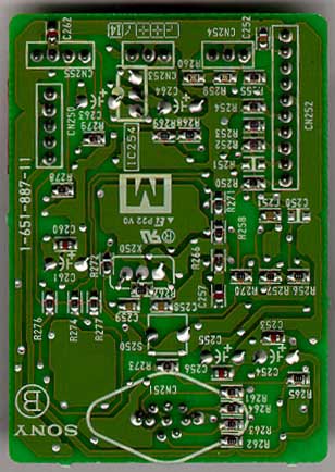
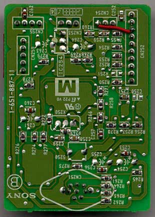
"Beforer and after"
To get Vsync to the 13W3 connector, remove the small PCB at the lower
right backside of the monitor. (the same PCB that holds the mini-DIN
connector at the back), and solder a small wire from CN252 to CN254,
as shown above (leftmost pin of CN254 and 3:rd from the top of CN252
in the pictures).

In case your monitor came with no connector attached, all 10 non-coax
pins from the male 13W3 that should have been atthed end of the cable,
terminates in CN252 on the same little PCB.

The three coaxes should be easy to identify, one red, green and blue
(my green was brown).

Numbered down-up, CN252 is connected to 13W3 like:

CN252	 13W3  color (in my monitor)

 1	  1    brown
 2	  8    black

 3	  6    yellow
 4	  9    green

 5	  2    red
 6	  4    orange

 7	  3    blue
 8	  7    purple

 9	  5    white
10	 10    grey

So if everything is clear so far, you should have soldered to the
third pin from the top of CN252, pin number 8 (purple), and that is
pin 7 in the 13W3, v-sync.
|
|


 "Beforer and after"